
Any current more than 5mA will damage the transistor, hence a resistor is always connected in series with the base pin. The biasing current should be not more than 5 mA.

This biasing can be done by providing the required amount of current to the base pin. When we supply current to the transistor's base, it makes a path for the collector current to flow from the base to the emitter.ĭuring Forward Bias, the transistor will act as an Open switch, and during Reverse Bias, it will act as a Closed switch. When a transistor is used as a switch it is operated in the Saturation and Cut-Off Region.
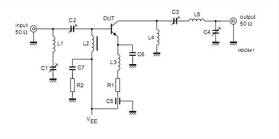
We must supply current to the base pin of a transistor to operate it, and this current (IB) should be limited to 5mA. The maximum current that can flow through the Collector pin is 100mA, we can't use this transistor to connect loads that use more than 100mA. The gain value of the BC547 transistor ranges from 110 to 800, and this value determines the transistor's amplification capacity. For instance, the best FM transmitters can associate with cell phones and mp3 players to communicate, and broadcast music and web recordings.This transistor is commonly used for amplification of current as well as switching purposes. The FM transmitter ought to associate with various gadgets.You can control this FM transmitter circuit with any size/sort of 1.5V or 3V battery. The least receiving wire or antenna length ought to be 12 inches however on the off chance that you need to expand the range, at that point increment the radio wire length to 30 inches. Furthermore, stop where you found the sound of your music. At that point set your FM radio recurrence or frequency on a clear spot and marginally change the transmitter’s trimmer with a nonconductive instrument. In the wake of making the circuit, apply control and associate it to the sound yield of your FM transmitter device. At the nearby inductor, there is a 1-30 pF trimmer capacitor, which is utilized to alter the recurrence or frequency of this mp3 FM transmitter. Moreover, evacuate the structure in the wake of winding the inductor. The circuit reference here can likewise operate in such a way that the inductor L1 is equivalent to 8 to 10 turns of 22 enameled wire twisted on a 6mm structure.


 0 kommentar(er)
